Cheetah Splice-On Connector Installation Instructions
FIS Cheetah 900µm Splice-On Connector Instructional Video
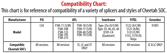
Note: This Splice-On Connector is compatible with 900µm optical fiber.
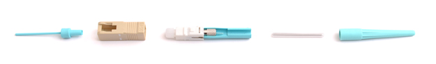
The Cheetah Splice-On Connector Contains the Following Items:
A. (1) Universal dust cap with extension handle
B. (1) Outer housing (SC style only)
C. (1) Splice-On Connector (SOC) pigtail with cleave protector and fiber alignment sleeve
D. (1) 27mm mini splice sleeve
E. (1) Universal strain relief boot
F. (1) Fiber positioning tool (Not Pictured)
Note: If fiber alignment sleeve has become separated from the SOC body, do not attempt to re-install, discard it and continue with cable preparation (SC and LC styles only).
CABLE PREPARATION
Slide the 900µm strain relief boot and then the 27mm mini splice sleeve onto the 900µm field fiber. Strip, clean, and cleave the field fiber to a 10mm cleave length per standard fiber optic stripping practices. Insert the cleaved fiber into the left-hand fiber holder of the fusion splicer. Make sure to butt the 900µm buffer up to the edge of the fiber holder. This will ensure that the mini splice sleeve will adhere to both sides of the 900µm buffer.
1. Remove the factory dust cap from the connector.
Note: The extended dust cap may be placed on at this time, if so desired, to aid in the transfer of the connector. DO NOT leave THE EXTENDED DUST CAP on the connector, inside the fusion splice machine.
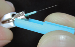
2. While holding the connector firmly, pull down on the cleave protector to remove it from the connector (Figure 1).
Note: Do not touch the cleaved fiber stub with the protector or your fingers as this may damage the factory cleave.
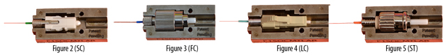
3. Insert the connector into the Universal Splice-On Connector Holder so that the back end of the connector is flush with the end of the holder (Figures 2-5). Once aligned properly, the connector should fit freely into the holder with no force required.
4. Insert the holder into the right hand side of the splicer (Figure 6), being sure that the fiber stub lays properly into the v-groove block of the splicer (Figure 7). You may use the fiber positioning tool to help align the fiber in the v-groove.
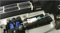
Figure 6 (Note: Remove the Extended Dust Cap Before Initiating the Fusion Splice)
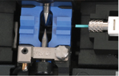
Figure 7
5. Perform the fusion splice as described in the fusion splicer manufacturers instructions.
6. Once the fusion splicing cycle is completed, remove the connector from the splicer and slide the splice protection sleeve up to cover the splice. An equal amount of the sleeve should cover the 900µm buffer on either side of the splice.
Note: The extended cap may be put in place now to aid in the transfer to the splice sleeve oven.
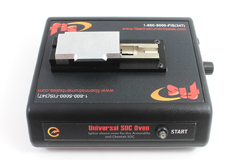
7. Transfer the splice to the splice sleeve heat oven. Verify the position of the splice sleeve and initiate the heat cycle.
Note: The Splice-On Connector Sleeve Oven is specifically designed for use with the Splice-On Connector. Re-check the correct position of the protection sleeve on the fiber, then lower the oven shield. Press the START button to run the shrink cycle (Figure 8).
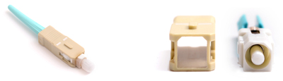
Figure 9
8. Verify that the splice protection sleeve is completely shrunk onto the fiber to avoid the end catching on the strain relief boot. If the splice sleeve is not completely shrunk, then place it back in the sleeve oven and initiate a second heat cycle.
Note: Make sure that the splice sleeve has fully cooled before sliding the strain relief boot into place. For SC connectors, install the outer housing onto the connector, being sure to align the angled corners of the inner housing with those of the outer housing (Figure 9).