Tier 1 versus Tier 2 Fiber Optic Testing

We can all agree that it’s great having today’s high bandwidth optical networks to fulfill our needs within our daily lives.
While the capabilities that these networks provide cannot be matched, their higher sensitivity to back reflection and attenuation can be a constant concern. As the internet takes over more and more of our daily regimens in business, entertainment, etc. this concern becomes elevated.
Because of these reasons, end users are ever more reliant on the constant reliability of these networks to support their day to day usages. This makes the selection and use of the proper test equipment so much more important today than it was, say a decade ago.
Within the industry there are two different levels or “tiers” for certifying a fiber optic network drawn up by the Telecommunications Industry Association (TIA): Tier 1 and Tier 2 testing. Depending which tier is required, specific test equipment is needed. Tier 1 is traditionally a simple test for attenuation, continuity, and polarity. Most times this testing can be achieved with a basic power meter and light source set, also known at an optical loss test set (OLTS).
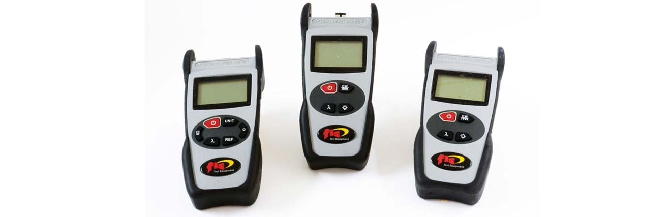
Tier 1 testing is primarily done with a power meter and light source
It involves using one or two reference cords You typically would use one reference cord if you are either testing a short patch cord or a spool of cable. This method leaves the last connector under test that plugs into the power meter untested, so you have to flip the ends around and run the test a second time to get a proper reading of both terminating connectors.
Two reference cords are typically used when each end of the cable is in two difference locations. This way the meter and the source each have a cord to plug into the cable under test. With this test method, both terminating connectors are being characterized within one test. In order to perform a test for loss (dB) the user must set up a reference first by using one of these two methods.
Tier 1 Testing Procedure
1. Turn on the power meter and the light source. It’s important that you let the light source run for 1-2 minutes to stabilize so you get more consistent results.
2. Note that the power meter when turned on will always default to be in dBm units (absolute power). You need this reading before a reference is taken.
3. Take one or two reference cords for whichever type of fiber you are testing (SM, 62.5um MM, or 50um MM)
4. Connect the ends of the reference cord(s) to your power meter and light source. If you are using two reference cords, make sure you clean and mate the two ends and mate them together. When done taking the reference you then would disconnect the two cords from each other and introduce the cable to be tested in the middle.
5. If testing Multimode fiber, make sure to use the appropriate mandrel on your reference cord to strip out the higher modes of light that may exist in the cladding. SM does not need a mandrel.
6. Now take a reference reading of the absolute power value (dBm) by pressing the REF button or ZERO button on the meter.
7. Your reference has been stored and the meter now should read 0.00dB. It is now ready to measure loss relative to the cable you will be testing.
8. If using one reference cord disconnect from the power meter side. Then connect the test cable onto the open end of the reference cord and plug the other end of the test cable into the power meter.
9. Now, if using two reference cords, disconnect them from the mated connectors in the middle.
10. Take the power meter with the open connector at the end of your reference cord to plug into terminated cable being tested. Also, take the light source with the open connector at the end of the other reference cable to plug into the opposite end of the terminated test cable.
11. View dB loss reading…
Tier 2 Testing with an OTDR
Tier 2 Testing is a bit more comprehensive. It involves an Optical Time Domain Reflectometer (OTDR) and in addition to measuring attenuation, it can measure back reflection, optical return loss (ORL) and give a pass/fail status for each event, whether reflective or non-reflective on the cable. This is what would need to be done to “certify” a network. The OTDR has the ability to characterize events and faults on the cable with several connections and shorter jumpers connecting patch panels. It will also certify the length of the cable allowing you to formulate a loss budget. .
Learn More about Power Meter & Light Source Operation
https://www.fiberinstrumentsales.com/video-category/power-meter-and-light-source-testing
Learn More About OTDR Operation
https://www.fiberinstrumentsales.com/video-category/otdr-operation