What Is a Fiber Optic Attenuator?

In telecommunication, a fiber optic attenuator is a component that is used to reduce transmitted signal strength at the receiver. Ordinarily you might think that the stronger the signal the better. This is not actually the case. There are a few reasons why you might want or need to use an attenuator in your system.
There is such a thing as a signal being too strong. Transmitters and receivers are designed to work together with the transmitter ideally sending a signal that the receiver can handle without issue. However, especially in singlemode fiber optic telecommunication networks, it is possible that the signal sent out over the fiber by the transmitter is too strong for the receiver to be able to read without distortion or damage to the receiver. This is one instance when you may need to use an attenuator. If you do not decrease the signal strength, the receiver can be overwhelmed by the amount of power that is coming at it, and as a result it may not interpret the signal correctly. Not only is it possible that the receiver may not be able to read the signal correctly, but if the power coming into the receiver is too great, it can damage the receiver by burning out the detector inside. This situation most often happens over short links in a singlemode network.
Attenuators are most effective at the receiver end of the link for a couple of reasons. Placing it near the receiver allows the signal strength to be conveniently measured and for it to be adjusted if necessary. Ideally, you want the signal strength to be in the middle of the range that the receiver can handle. The correct amount of attenuation needed can be determined either during the design stage or it can be determined after installation by performing a power meter and light source test.
If the level of attenuation needed for the system to work well is determined during the design phase, the system architect will need to determine the Power Budget. The power budget for a fiber optic link or network refers to the amount of light that is needed to successfully transmit signals over the cable plant. Some of the factors that will affect the power budget are chromatic dispersion (CD) and polarization mode dispersion (PMD), mated connector pairs, mechanical and or fusion splices, the length of the cable plant, and the loss that is inherent in the optical fiber itself. The system power budget can be determined by the power level specification coming from the transceiver and the loss that is inherent in the network plant cabling, and then subtracting the minimum amount of power that the receiver can accept and still be able to correctly interpret the signal.
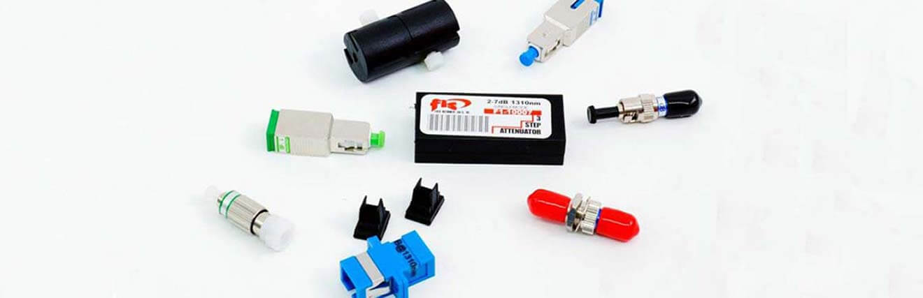
There are several different kinds of attenuators. There are air gap attenuators which create a small space (air gap) between two mated fibers. There are also step attenuators that create attenuation by making tight loops in a patch cable which creates loss in signal as some of the light escapes the core of the fiber creating the needed attenuation. Clip on attenuators are another mechanical method of creating attenuation. This type of attenuator goes around the outer cable jacket and then the jacket is “pinched” creating loss of light on the fiber inside the cable and this creates the attenuation.
Air Gap Attenuator
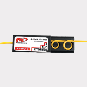
Step Attenuator
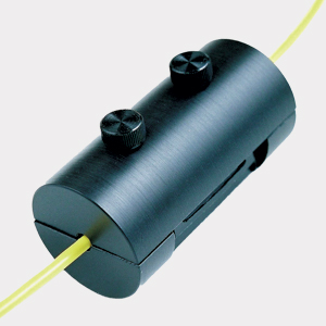
Clip On Attenuator
There is another type of mechanical attenuator that uses a method that is a bit more complicated than the ones we talked about just above here. A variable attenuator uses collimator lens technology that enables the user to change the level of attenuation by twisting a top mounted screw that adjusts the collimator lens. This variable attenuator can be used to simulate the loss in a fiber system or to test the system’s dynamic range. A power meter and light source can be used to determine the fixed attenuation value your system requires.
In addition to variable attenuator patch cables, there are also fixed inline attenuators. The fixed inline attenuator is essentially a patch cable that has a measured amount of attenuation at a particular wavelength built into the assembly. This type of attenuator is very good for low reflection requirements and the connector ends are either UPC or APC polished to maintain the low reflectance properties.
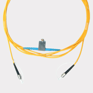
Variable Attenuator
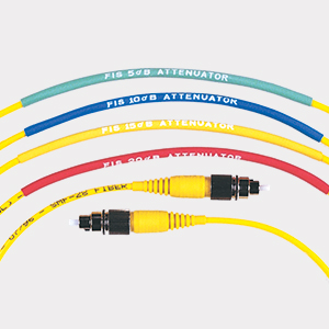
Fixed Inline Attenuator
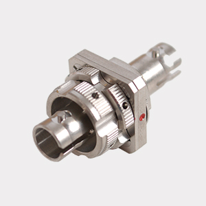
FDDI Fixed Attenuator
Male to Female Fiber Optic Attenuators or Build Out Attenuators can be used to decrease the transmitted signal strength, usually at the receiver. This type of attenuator has a fiber optic connector (male) on one side and the other side is a fiber optic mating sleeve or adapter (female). These attenuators feature a fixed level of attenuation, they are not variable. Male to Female attenuators are the most commonly used type of attenuator. They are available in all of the most common connector styles - LC, SC, ST and FC, and attenuation levels will vary from 1dB to 20dB in most cases, although other levels are available. The attenuation is achieved by using doped fiber in the attenuator. Rare earth metals or elements are used to achieve the doping of the fiber. Often these attenuators are optimized for 1310 and 1550nm wavelengths. They have a tolerance that users should be aware of, 1-10dB +/-0.5dB and 11-30dB +/- 5% of the attenuated level.
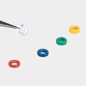
Bulkhead Style attenuators are essentially fiber optic mating sleeves or adapters or couplers. Like the Male to Female Attenuators, the attenuation is achieved using rare earth doped optical fiber inside the attenuator. Bulkhead attenuators are female on both sides. In other words, both sides of the attenuator accept male fiber optic connectors. These too are available in the most common connector styles, LC, SC, ST and FC. They are also available with various levels of attenuation. This type of attenuator is optimized for 1310nm or 1550nm wavelengths. Their tolerances are +/-0.5dB for 1dB to 10dB levels of attenuation, and +/-56% of the level of attenuation for 11 to 30dB.

Bulkhead Attenuator
In conclusion, more power is not always a good thing. There really is such a thing as too much power. You can think of attenuators as the “sunglasses” of a fiber optic network, allowing the receiver to clearly see the signal being sent from the transmitter.